
How to Convert 2D Images to Watertight 3D STL Files for 3D Printing
A comprehensive engineering guide on turning JPG and PNG images into 100% watertight, sliceable 3D STL models without non-manifold edge errors in Bambu Studio, Cura, or PrusaSlicer.
 EasyToSTL Team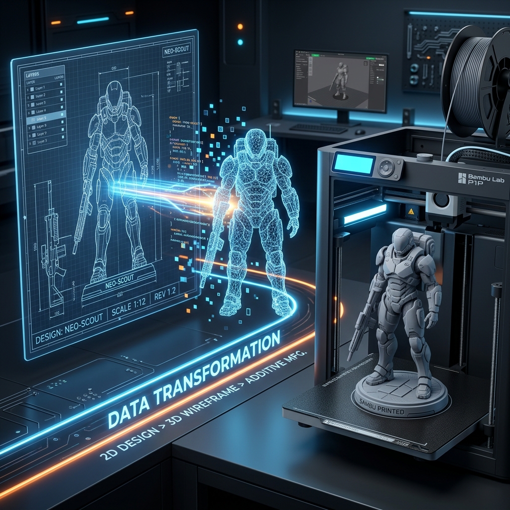
Transforming a 2D digital image into a physical 3D object has long been a dream for makers, product designers, and 3D printing enthusiasts. Until recently, bridging the gap between 2D pixels and a solid 3D mesh required either painstaking manual sculpting in Blender or crude heightmap extrusion (lithophanes) that produce flat-backed reliefs rather than true volumetric solids.
With modern AI-driven spatial reconstruction, you can now generate fully closed, watertight 3D models directly from a single reference image or concept sketch.
However, anyone who has ever loaded an AI-generated model into Bambu Studio, OrcaSlicer, PrusaSlicer, or Ultimaker Cura knows the dreaded warning:
"The uploaded STL file contains non-manifold edges. Auto-repaired 1,420 inverted faces."
In this guide, we break down why typical 2D-to-3D tools fail slicer inspections, what "watertight" actually means in additive manufacturing, and how to follow a foolproof workflow to convert your 2D images into flawless 3D prints.
1. Why Standard 2D-to-3D Conversions Fail Slicer Checks
3D printers do not understand visual "surfaces"; they understand enclosed physical volumes. When a slicer slices a model into layers (G-code), it calculates the boundary between inside the solid plastic and outside in the air.
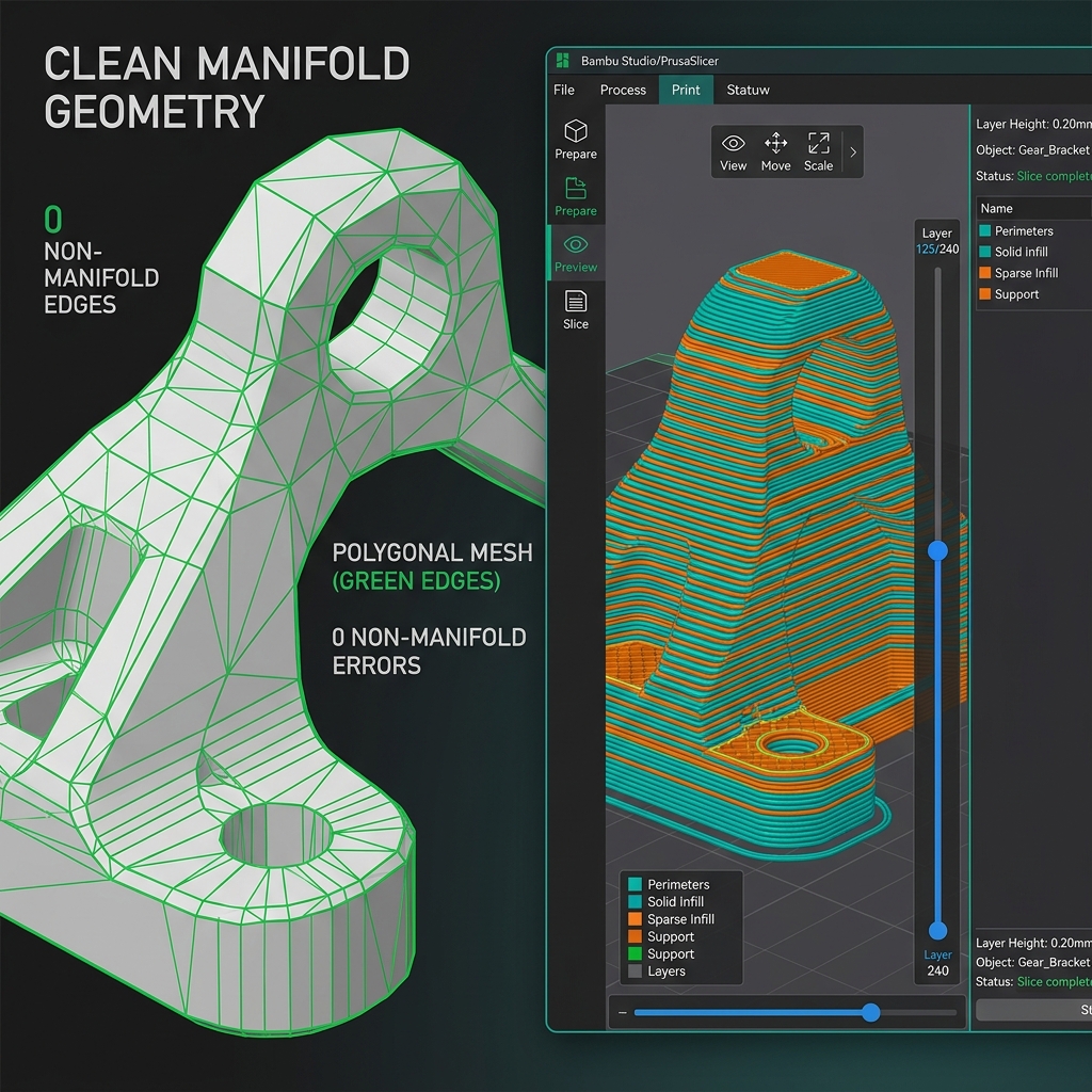
When an AI model produces faulty geometry, you run into three critical issues:
- Non-Manifold Edges (Open Shells): An edge is shared by fewer or more than two faces. The slicer cannot determine what is solid infill and what is empty space, leading to missing layers or spaghetti infill.
- Inverted Surface Normals: Facets point inward rather than outward. The slicer interprets your object as an "inside-out vacuum," causing hollow voids or phantom extrusions.
- Internal Intersecting Geometry: Multiple disjointed sub-meshes intersecting each other. This creates double-extrusion paths, nozzle grinding, and surface scarring during printing.
The Comparison: Traditional vs Modern AI Reconstruction
| Feature | Legacy Heightmaps / Lithophanes | Raw 3D Generative Models | EasyToSTL Watertight Engine | | :----------------------- | :------------------------------ | :------------------------------------ | :---------------------------------------------- | | Geometry Type | 2.5D Bas-Relief (flat back) | Hollow point clouds / messy surface | True 360° Volumetric Solid | | Slicer Compatibility | High (basic box) | Poor (hundreds of non-manifold edges) | 100% Watertight (0 Repair Warnings) | | Physical Scaling | Manual scale factor guess | Unitless coordinates | True Millimeter (mm) Precision | | Supported Slicers | Any basic slicer | Requires Netfabb or Meshmixer repairs | Bambu Studio, OrcaSlicer, PrusaSlicer, Cura |
2. Step-by-Step: From 2D Image to 3D Print
Here is the exact step-by-step workflow recommended by our engineering team to convert your design into a print-ready model.
Step 1: Prepare Your Source Image
AI reconstruction models infer depth, curvature, and volumetric occlusion from contrast, lighting gradients, and silhouette clarity.
For the highest fidelity result:
- Clean Background: Use a neutral or transparent background so the AI model clearly separates the foreground subject from the backdrop.
- Isometric or Three-Quarter Angle: A slight angle reveals both the front profile and top/side perspective, allowing the neural engine to extrapolate back geometry with high fidelity.
- Avoid Heavy Motion Blur or Film Grain: Crisp vector illustrations, concept art, character designs, logos, and high-contrast photography yield the sharpest geometric features.
Step 2: AI Mesh Reconstruction with Closed Manifold Constraints
Upload your image to the EasyToSTL AI Converter. The underlying engine processes the 2D input through a specialized volumetric neural pipeline that strictly enforces a closed 2-manifold topology:
2D Pixel Array (JPG/PNG)
       ↓
Depth & Normal Estimation Fields
       ↓
Volumetric Implicit Surface Generation
       ↓
Marching Tetrahedra / Dual Contouring
       ↓
100% Watertight Closed STL / GLB Mesh
By ensuring every geometric edge belongs to exactly two triangular faces, the resulting mesh leaves zero holes or inverted normals.
Step 3: Calibrate Physical Dimensions in Millimeters (mm)
Unlike game engines where models have arbitrary unitless dimensions, 3D printing requires precise millimeter coordinates.
In our interactive 3D viewer:
- Rotate and inspect your model from all 360 degrees.
- Check the real-time bounding box dimensions ((X \times Y \times Z) in mm).
- Set your target height (for instance, 80 mm for a desk miniature or 150 mm for an anime figurine). All dimensions scale proportionately while maintaining aspect ratio.
Step 4: Validate in Your Preferred Slicer
Download the exported binary .stl file and drag it directly into your slicer of choice:
- Bambu Studio / OrcaSlicer: Observe the model status in the bottom right corner — you will see 0 non-manifold edges and no yellow exclamation warning icons.
- PrusaSlicer: The auto-repair counter remains at 0.
- Ultimaker Cura: The X-ray view shows solid green without red non-manifold error faces.
3. Practical Print Settings for Best Results
Once your model is in the slicer, choose optimal settings depending on your printer type:
For FDM Printers (Bambu X1C / P1S / A1, Prusa MK4, Ender 3)
- Layer Height:
0.12 mm-0.16 mmfor high detail miniatures;0.20 mmfor functional brackets. - Wall Loops (Perimeters): At least
3 wallsto give the outer shell structural rigidity. - Supports: Enable Tree Supports (Auto) with a threshold angle of
30°. Tree supports leave minimal surface blemishes on organic curves and pop off cleanly. - Infill:
12% - 15% Gyroidinfill provides uniform multi-directional strength without internal vibration resonance.
For Resin (SLA / MSLA) Printers (Elegoo Saturn, Anycubic Photon)
- Hollow and Vent: If printing larger than 70 mm, hollow the model with a
2.0 mmwall thickness and add at least two drain holes near the build plate base to prevent suction cups. - Orientation: Angle the model back at
30° - 45°relative to the build plate to minimize cross-sectional peel force per layer.
4. Explore Free In-Browser 3D Inspection & Conversion Tools
Beyond AI image generation, our platform provides completely free, client-side 3D utilities:
- Universal 3D Viewer: View and inspect STL, GLB, GLTF, OBJ, and FBX files in real time directly in your browser without installing heavy software.
- STL Viewer: Check physical bounding box dimensions, triangle counts, and surface normals.
- Universal 3D Converter: Convert existing models between GLB, OBJ, PLY, and slicer-ready STL format with 100% private in-browser WebAssembly processing.
Conclusion
Creating custom physical objects no longer requires hundreds of hours mastering complex 3D CAD modeling suites. By combining clean reference imagery with an AI converter engineered specifically for watertight additive manufacturing, you can go from a 2D sketch to a finished 3D print in under an hour.
Ready to bring your ideas to life? Try out the EasyToSTL Converter today and claim your free welcome credits!